ABSTRACT
Electricity exists in a form that is useful to exploit, however, it will also be important to install electricity as efficiently as possible, and design of the power distribution system should be convenient so as to minimize power losses. This paper analyses the electrical service design of a Storey building using the lumen method for the lighting calculations. The purpose of this work is to present a suitable approach to electrical services design based on the provision of the Institution of Electrical Engineers (lEE) Regulations, which includes lighting, power, distribution boards schematics. The results of the whole analysis and design was illustrated with AutoCAD application. This work gives a direct approach from design of the electrical services to the installation stage. The results of the calculations in the design helps the designer to make vital decisions such as types of luminaries, sizes of cables and nominal ratings of protective devices required by each circuit and by the entire installation in line with appropriate standards and regulations.
INTRODUCTION
Every electrical installation be it residential, commercial or industrial buildings is preceded by a careful plan or design. Designs for building installations involves various calculations based on several factors which includes; type of building, purpose of building, physical building parameters. (Olatomiwa, et al. 2012). There are several Standards and regulatory bodies such as the IEE (Institute of Electrical Engineers), BSS (British Standard Specification), NEC (National Electrical Code), NERC (Nigerian Electricity Regulatory Commission), IES (Illuminating Engineering Society) and NESIS (Nigerian Electricity Supply and Installation Standards) and many more that regulate the electrical service design. Electrical design is the process that involves planning, creating, testing, and installation of electrical equipment in accordance with the approved regulations, the design includes lighting layout, power layout, power distribution layout, fire prevention layout systems, public address system and close circuit TV layout and voice and data communications layout design. (learn, 2019).
The important area covered in this paper are: Lighting layout design, Power layout design, Cables sizing, Protection system design. Electricity exists in a form that is useful to exploit, however, it will also be important to install electricity as efficiently as possible, and design of the power distribution system should be convenient so as to reduce power losses and voltage drops. Every building or part of building apartment illumination level varies in terms of illumination level, number of socket outlets, accessories and electrical appliance. The illumination level of each portion is different depending on the purpose it is really meant for. The design was based strictly in accordance with the institution of electrical engineers (lEE) Regulations and several standard regulatory bodies while adequate provisions were made for flexibility so as to make provision for future expansion. Many factors were put into consideration during the design. Some of these include safety, durability, flexibility of installation, and cost of installation.
METHODOLOGY
There are two essential methods for determine the type of luminaires to be use. The two key methods are called the point by point method and the lumen method.
The Point by Point method which is also known as inverse square law can be used to determine what is needed to produce a given level of illumination on a given area. This approach is not used often because of its complexity and its limitations. It is mostly used when there is need to determine the illumination levels produced by single or multiple fixtures for flood lighting and recess lighting, while the Lumen method of lighting design is a frequently used approach of lighting design, which is acceptable, if the lighting luminaires are to be installed overhead in a conventional pattern. In this project the lumen method was used to calculate the lighting point needed in each room and the total lumen is expressed mathematically as follows.
Where,
N = the number of lamps required.
E = the illuminance level required (lux) A = area of the working plane height (m2)
∅ = the average luminous flux from each lamp (lm)
MF= maintenance factor, an allowance for reduced light output due to deterioration and dirt.
UF= utilization factor, an allowance for the light distribution of the luminaire and the room surfaces.
-
Lighting Design Calculation
For the calculation, the table below shows building area with their different illumination levels. Table 1.0 showing the values for illuminance (IES lighting handbook)
Table 1.0 showing the values for illuminance (IES lighting handbook)
| Building Area | Light level (lux) |
| Living room / den | 150 – 500 |
| Bedroom, Dormitory | 150 – 300 |
| Kitchen | 150 – 300 |
| Hall, landing / stairway | 100 – 500 |
| Restroom / toilet | 150 – 300 |
| Cafeteria – eating, dinning | 150 – 300 |
| Store | 150 |
| Lobby – office, corridor, Veranda | 150 – 300 |
Source: Illuminating Engineering Society (IES) lighting handbook
-
Lighting Points Required On the Ground Floor
Table 2.0 and 3.0 below shows the room type with the calculations of how the number of luminaire to be used is determined, and the type of luminaire used is Compact fluorescent lamp (also known as energy saving lamp), in this design three major types of wattages used are: 16W, (1100 lumen); 26W, (1600 lumen) and 50W, 4800 lumen respectively.
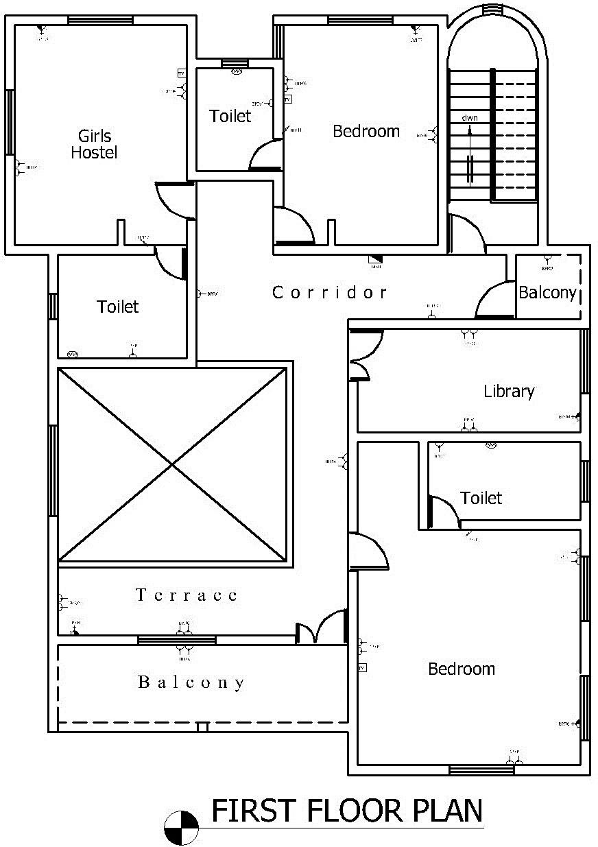
Table 4.0: Lumen method calculation for the first floor
| S/N | Room Type | Number of Luminaire to be used | |
| 1. | Balcony | 2 | |
| 2. | Master Bedroom | 6 | |
| 3. | Master Toilet | 1 | |
| 4. | Wardrobe | 1 | |
| 5. | Library | 4 | |
| 6. | Girls Hostel | 5 | |
| 7. | Girl Hostel Toilet | 1 | |
| 8. | Terrace | 8 | |
| 9. | Bedroom | 3 | |
| 10 | Bedroom Toilet | 1 | |
| 11 | Corridor | 3 | |
| 12 | Small Balcony | 1 |
RESULTS AND DISCUSSION
After carried out the appropriate calculation in accordance with required regulations and standard, the aim and objectives of the paper was achieved. The following sections explains the analysis of the results.
-
Electrical Legend
It is a standard symbol that shows a collection of graphical representation used with detailed records of all electrical components and accessories used in a design such as light, fan, cooker control unit, switches, air conditioner etc. Fig. 1.0 displayed electrical legend of all symbols used in this design.
-
Lighting Design Layout
This is the design of electrical system that shows lighting layout positions and how they are interconnected to one another. Lighting design layout includes the following: lighting fittings, ceiling fans, extractor fan, switches, etc. Fig. 2.0 and 3.0 displayed electrical lighting layout design for ground floor and first floor respectively.
-
Power Design Layout
This is the design of power rating equipments that allow for the supply and distribution of electrical power through a network to the require load. Power design layout includes the following: Socket outlets, Water heater outlets, Air Conditioner connections points, Distribution boards, Telephone outlets, TV / Satellite receiver outlet, Data cable outlet, etc. Fig. 4.0 and 5.0 displayed electrical power layout design for ground floor and first floor respectively.
-
Load Analysis for Distribution System
An electrical distribution system is the equipment that distribute all load to final sub-circuit in an electrical installation. It includes the main switchboard, which receives the power source from the serving utility, and all the associated components such as panel boards that distribute all the required branch circuits throughout the facility. Part of the process of designing the distribution system is to quantify the total load which helps in load balancing and appropriate selection of the approved distribution board, these calculations shows the total electrical demand requirements of the facility. Fig. 6.0 and 7.0 displayed a load analysis of a balanced distribution board for ground floor and first floor respectively.
P = 3IVCOS ; Where P is the total load in KW, I current demand is Amps, V is the voltage, Cos∅ is the power factor
Note: 100A, 6-Way TP&N Distribution board with 100A MCB mains circuit protection is recommended, in order to create provision for future expansion.


CONCLUSION
In this paper, the lumen method was used for the lighting layout design and the power layout was achieved by using the laid down standard table for power as specified by IEE regulation. Appropriate ratings of protective devices are put in place and there is adequate provision for future expansion. The results of the calculations in the design helps to make vital decisions such as types of luminaries, sizes of cables and nominal ratings of protective devices required by each circuit and by the entire installation in line with appropriate standards and regulations, with this design, it is evident that the proposed building will be safe from electric fire outbreak. All cables presented to be used were calculated to the specified standard in accordance to IEE regulations and other regulated bodies.
The electricity Standards and regulatory bodies should enact a law that will make all builders to provide an approved standard electrical service drawing before any electrical installation must be carried out.
REFERENCES
- Adelakun, N. O. (2018) Electrical Service Design of a Proposed Multipurpose Building Complex,
B.Sc. Thesis, Faculty of Engineering, Olabisi Onabanjo University, Ago – Iwoye, Ogun State, Nigeria.
-
- Adeshina Mohammad Awwal (2015) Electrical Services Design of a Proposed One Storey Two Bedroom Twin Flat Residential Building, B.Sc. Thesis, Col. Of Natural Science, Ahmadu Bello University, Zaria, Kaduna State, Nigeria.
- Brian Scaddan (2008) 17th Edition IEE Wiring Regulations: Explained and Illustrated Eighth edition
- Byron G Byraiah (2016) http://www.wbdg.org/design-disciplines/electrical-engineering
- Darrell Locke (2008) Guide to the Wiring Regulations 17th Edition IEE Wiring Regulations (BS 7671: 2008)
- Fred Hall and Roger Greeno (2007). Building Services Handbook, fourth edition, Published by Elsevier Limited.
- Hacker (2011) Merrian-Webster: Electricity in Merriam-Webster.com Retrieved May 8, 2018, from https://www.merriam-webster.com/dictionary/electricity
-
- IESNA (2000), The IESNA Lighting Handbook, Ninth Edition, the Illuminating Engineering Society of North America
- John Hauck (2009) Electrical Design of commercial and Industrial building, Jones and Bartlett Publishers, LLC.
- Mohammed Mahmood Katoon (2009) A Project Report in Electrical Services Design for Three Bedroom Flat, B.Sc. Thesis, Faculty of Engineering, Federal University of Technology, Minna. Niger state, Nigeria.
- Oele O. C. (2011) Building Electrical Services Design for Hostel Along Nyerere Road, B.Sc.Thesis, Faculty of Engineering, University of Nairobi, Kenya.
- Okoye, C. U. & Adelakun, N. O. (2019), Design and Evaluation of Electrical Services for an Energy Efficient Home, Iconic Research and Engineering Journals, Vol. 3, Issue 6, Pp 95 – 102
- Olatomiwa, L. J. and Alabi, A. C. (2012) Design and Development of Calculator Software for Residential Electrical Services Design, International Journal of Engineering and Technology. Volume 2 No. 3.
- Paddock, J. O and Galvin, R. A. W. (1982). Electrical Installation Technology and Practice 13th Impression, London.
- Thereja, B. L and Thereja, A. K. (2005). A textbook of Electrical Technology, First Multicolour Edition, S. Chand & Company Ltd. Ram Nagar, New Delhi.
- learn.org/articles/What_is_Electrical_Design.html [Retrieved September 18, 2019]
- https://en.wikipedia.org/wiki/Electrical_wiring [Retrieved October 8, 2019]
- https://www.archtoolbox.com/materials-systems/electrical/recommended-lighting-levels-in buildings.html [Retrieved October 28, 2019]